dink 50 125 1 Werkplaats-Handboek : Bladzijde 130

Microfiches
Image preview

Bladzijde 128

Image preview

Bladzijde 129

Image preview

Bladzijde 131

Image preview

Bladzijde 132

1 5 10 15 20 25 30 35 40 45 50 55 60 65 70 75 80 85 90 95 100 105 110 115 120 125 130 135 140 145 150 155 160 165 170 175 180 185 190 195 200 205 210 215 220 225 230 235 240 245 250 255 260 265 270 275 280 285 290 295 300 305 310 315 320 325 330 335 340 345 350 355 360 365 370 375 380 385 390 395 400 405 410 415 420 424
          6. CYLINDER HEAD/VALVES                                                             DINK 50/ 125


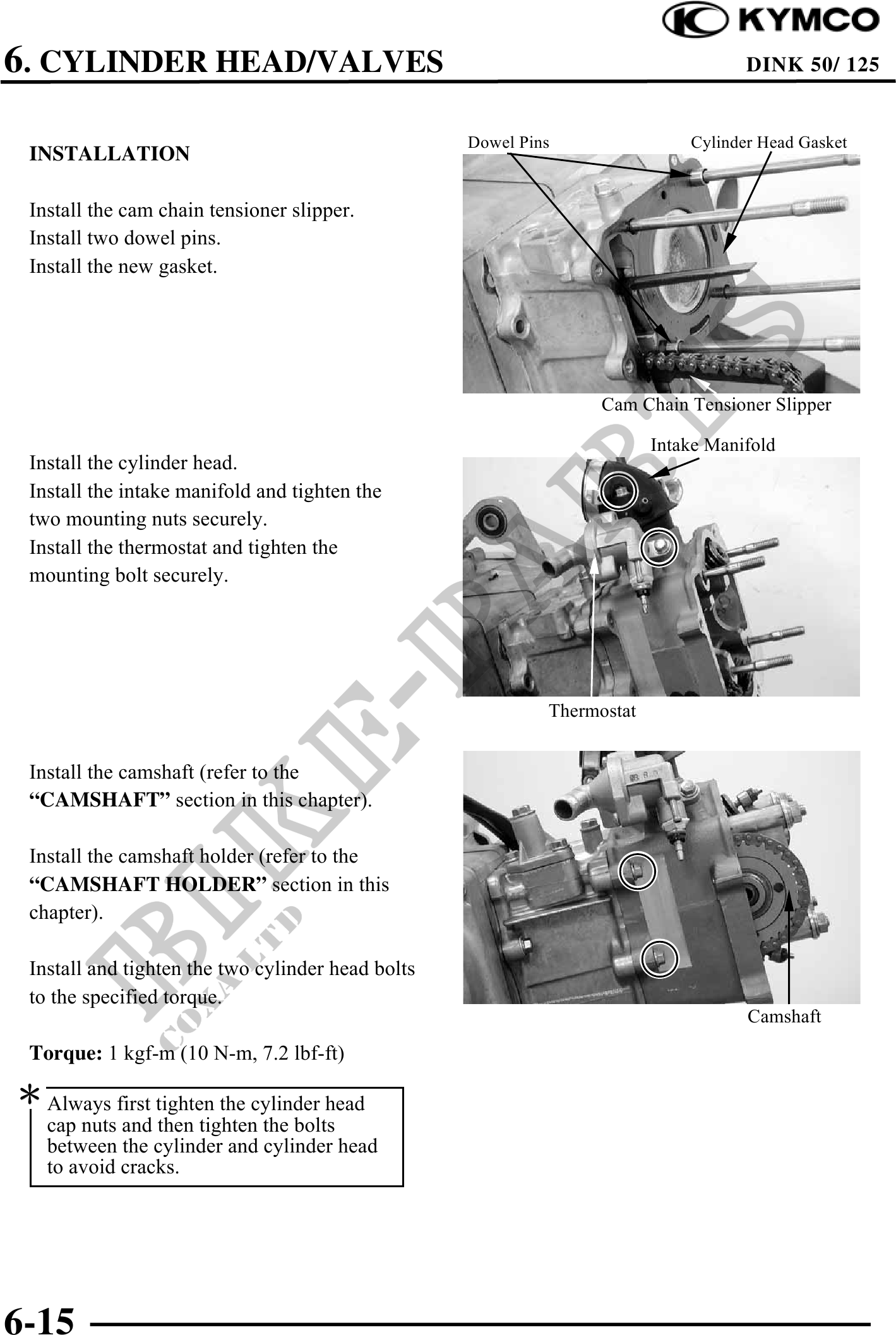
                                                   Dowel Pins                Cylinder Head Gasket
 INSTALLATION

 Install the cam chain tensioner slipper.
 Install two dowel pins.
 Install the new gasket.


                                                                  Cam Chain Tensioner Slipper
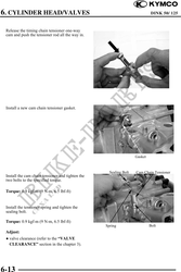
                                                                         Intake Manifold
 Install the cylinder head.
 Install the intake manifold and tighten the
 two mounting nuts securely.
 Install the thermostat and tighten the
 mounting bolt securely.


                                                            Thermostat


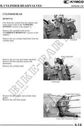
 Install the camshaft (refer to the
 "CAMSHAFT" section in this chapter).

 Install the camshaft holder (refer to the
 "CAMSHAFT HOLDER" section in this
 chapter).

 Install and tighten the two cylinder head bolts
 to the specified torque.
                                                                                    Camshaft
 Torque: 1 kgf-m (10 N-m, 7.2 lbf-ft)

 Always first tighten the cylinder head
   cap nuts and then tighten the bolts
   between the cylinder and cylinder head
   to avoid cracks.


6-15