3. INSPECTION/ADJUSTMENT DINK50/125
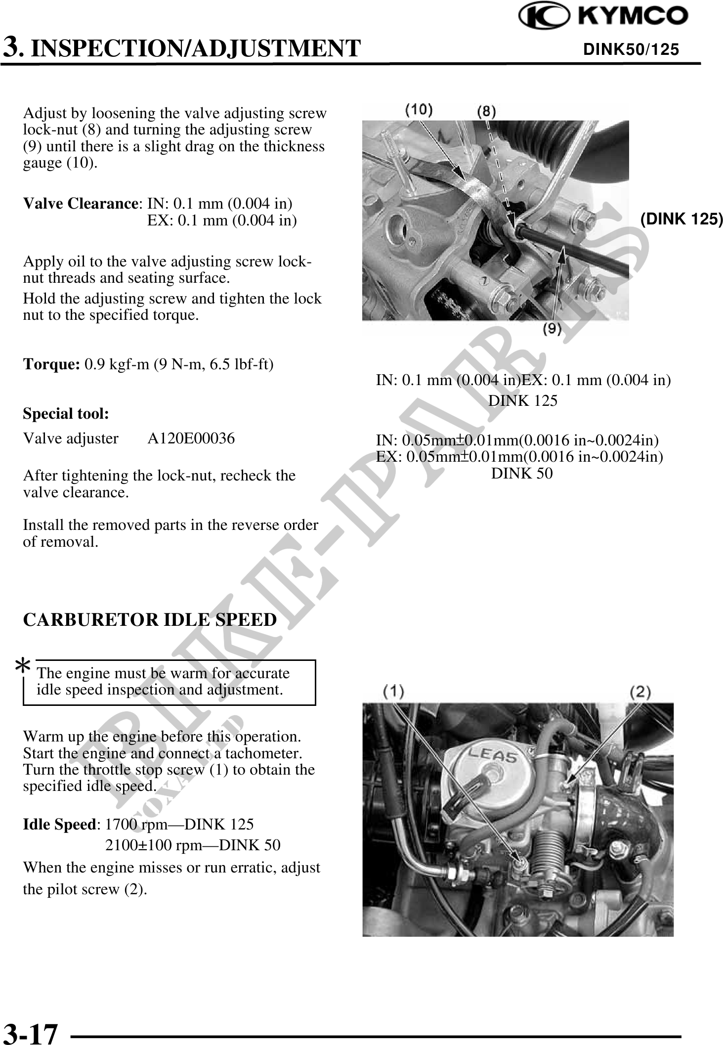
Adjust by loosening the valve adjusting screw
lock-nut (8) and turning the adjusting screw
(9) until there is a slight drag on the thickness
gauge (10).
Valve Clearance: IN: 0.1 mm (0.004 in)
EX: 0.1 mm (0.004 in) (DINK 125))
Apply oil to the valve adjusting screw lock-
nut threads and seating surface.
Hold the adjusting screw and tighten the lock
nut to the specified torque.
Torque: 0.9 kgf-m (9 N-m, 6.5 lbf-ft)
IN: 0.1 mm (0.004 in)EX: 0.1 mm (0.004 in)
DINK 125
Special tool:
Valve adjuster A120E00036 IN: 0.05mm0.01mm(0.0016 in~0.0024in)
EX: 0.05mm0.01mm(0.0016 in~0.0024in)
After tightening the lock-nut, recheck the DINK 50
valve clearance.
Install the removed parts in the reverse order
of removal.
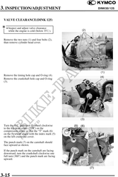
CARBURETOR IDLE SPEED
The engine must be warm for accurate
idle speed inspection and adjustment.
Warm up the engine before this operation.
Start the engine and connect a tachometer.
Turn the throttle stop screw (1) to obtain the
specified idle speed.
Idle Speed: 1700 rpm--DINK 125
2100100 rpm--DINK 50
When the engine misses or run erratic, adjust
the pilot screw (2).
3-17