dink 50 125 1 Werkplaats-Handboek : Bladzijde 175

Microfiches
Image preview

Bladzijde 173

Image preview

Bladzijde 174

Image preview

Bladzijde 176

Image preview

Bladzijde 177

1 5 10 15 20 25 30 35 40 45 50 55 60 65 70 75 80 85 90 95 100 105 110 115 120 125 130 135 140 145 150 155 160 165 170 175 180 185 190 195 200 205 210 215 220 225 230 235 240 245 250 255 260 265 270 275 280 285 290 295 300 305 310 315 320 325 330 335 340 345 350 355 360 365 370 375 380 385 390 395 400 405 410 415 420 424
          8. DRIVE AND DRIVEN PULLEYS/
  KICK STARTER                                                                   DINK 50/125
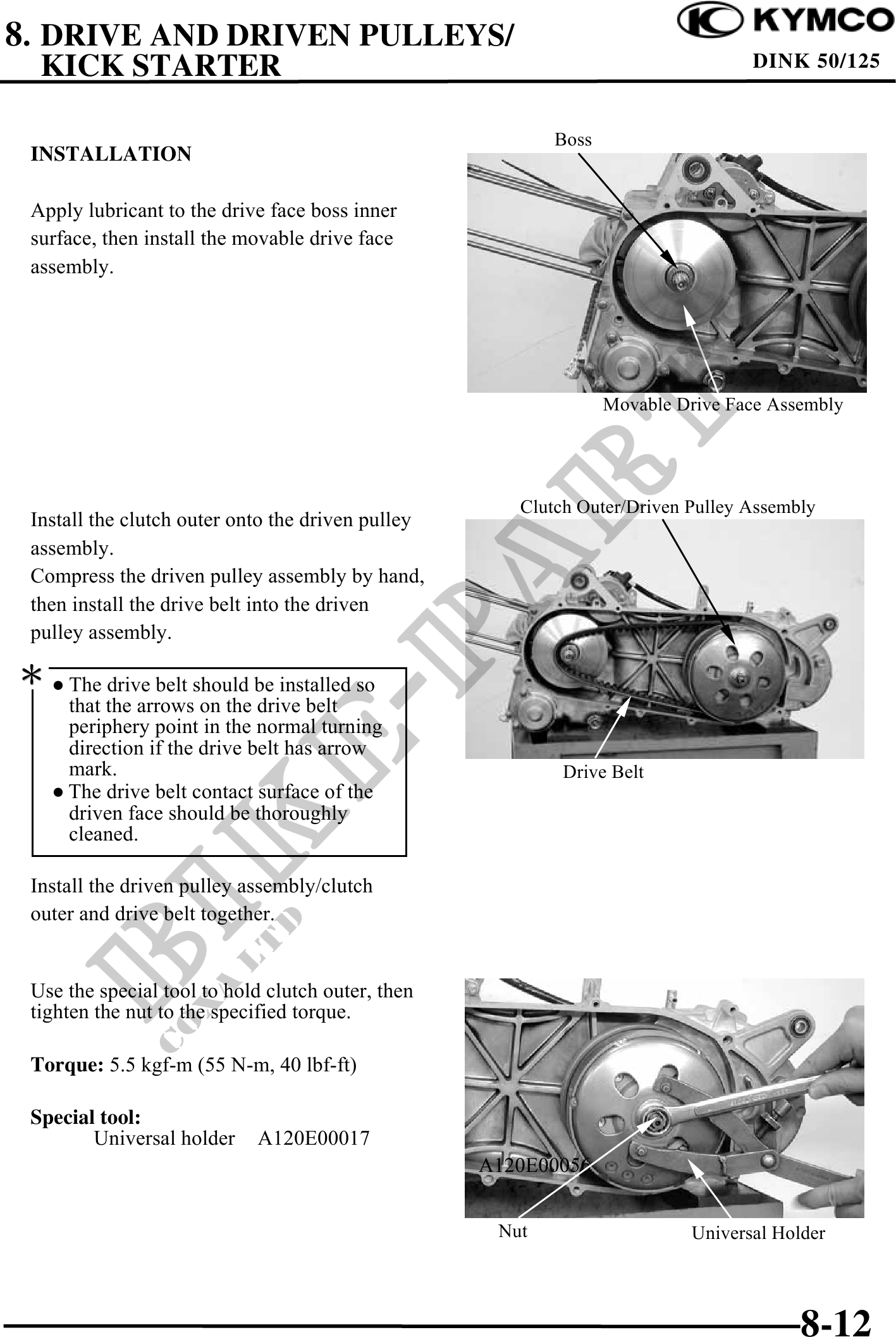

                                                          Boss
 INSTALLATION

 Apply lubricant to the drive face boss inner
 surface, then install the movable drive face
 assembly.


                                                                 Movable Drive Face Assembly


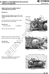
                                                      Clutch Outer/Driven Pulley Assembly
 Install the clutch outer onto the driven pulley
 assembly.
 Compress the driven pulley assembly by hand,
 then install the drive belt into the driven
 pulley assembly.

  The drive belt should be installed so
    that the arrows on the drive belt
    periphery point in the normal turning
    direction if the drive belt has arrow
    mark.                                                  Drive Belt
    The drive belt contact surface of the
    driven face should be thoroughly
    cleaned.

 Install the driven pulley assembly/clutch
 outer and drive belt together.


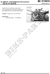
 Use the special tool to hold clutch outer, then
 tighten the nut to the specified torque.

 Torque: 5.5 kgf-m (55 N-m, 40 lbf-ft)

 Special tool:
        Universal holder    A120E00017
                                                   A120E00056


                                                    Nut                   Universal Holder


                                                                                       8-12