15. REAR WHEEL/SHOCK
ABSORBER/SWING ARM UXV 500
REAR WHEEL
REMOVAL/INSPECTION/
INSTALLATION
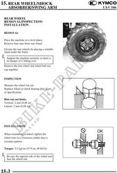
REMOVAL
Place the machine on a level place.
Remove four nuts from rear wheel.
Elevate the rear wheels by placing a suitable
stand under the frame.
Support the machine securely so there is
no danger of it falling over.
Remove the rear wheel and wheel hub nut
cap together.
INSPECTION
Measure the wheel run out.
Replace wheel or check bearing play if out
of specification
Rim run out limits:
Vertical: 2 mm (0.08 in)
Lateral: 2 mm (0.08 in)
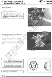
INSTALLATION
When reinstalling a wheel, tighten the
wheel nuts in a crisscross (rather than a
circular) pattern.
Torque: 5.5 kgf-m (55 N-m, 40 lbf-ft)
Be sure the tapered side of the wheel nuts
face the wheel rim.
15-3