Winkelwagen

| Produkt | Onderdeelnummer | Aantal |
|---|
| Produkt | Onderdeelnummer | Aantal |
|---|

20. LIGHTS/SWITCHES UXU 500
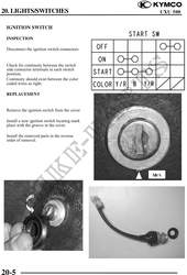
IGNITION SWITCH
INSPECTION
Disconnect the ignition switch connectors.
Check for continuity between the switch
side connector terminals in each switch
position.
Continuity should exist between the color
coded wires as right:
REPLACEMENT
Remove the ignition switch from the cover
Install a new ignition switch locating mark
place with the groove in the cover.
Install the removed parts in the reverse
order of removal.
Mark
20-5