Winkelwagen

| Produkt | Onderdeelnummer | Aantal |
|---|
| Produkt | Onderdeelnummer | Aantal |
|---|

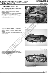
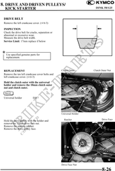
8. DRIVE AND DRIVEN PULLEYS/
KICK STARTER DINK 50/125
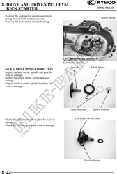
Kick Starter Spindle Forcing Part
Inspect the kick starter spindle and driven
gear forcing parts for wear or damage.
Kick Starter Spindle Forcing Part
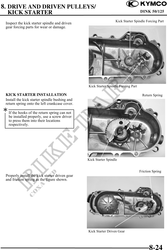
KICK STARTER INSTALLATION Return Spring
Install the kick starter spindle bushing and
return spring onto the left crankcase cover.
If the hooks of the return spring can not
be installed properly, use a screw driver
to press them into their locations
respectively.
Kick Starter Spindle
Friction Spring
Properly install the kick starter driven gear
and friction spring as the figure shown.
Kick Starter Driven Gear
8-24