14.HANDLEBAR/FRONT WHEEL/FRONT BRAKE/
FRONT SHOCK ABSORBER/STEERING STEM DINK 50/125
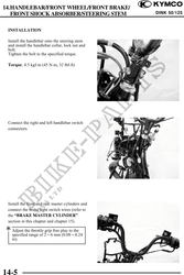
INSTALLATION
Install the handlebar onto the steering stem
and install the handlebar collar, lock nut and
bolt.
Tighten the bolt to the specified torque.
Torque: 4.5 kgf-m (45 N-m, 32 lbf-ft)
Connect the right and left handlebar switch
connectors.
Install the front and rear master cylinders and
connect the brake light switch wires (refer to
the "BRAKE MASTER CYLINDER"
section in this chapter and chapter 15).
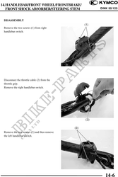
Adjust the throttle grip free play to the
specified range of 26 mm (0.080.24
in).
14-5