dink 50 125 1 Werkplaats-Handboek : Bladzijde 414

Microfiches
Image preview

Bladzijde 412

Image preview

Bladzijde 413

Image preview

Bladzijde 415

Image preview

Bladzijde 416

1 5 10 15 20 25 30 35 40 45 50 55 60 65 70 75 80 85 90 95 100 105 110 115 120 125 130 135 140 145 150 155 160 165 170 175 180 185 190 195 200 205 210 215 220 225 230 235 240 245 250 255 260 265 270 275 280 285 290 295 300 305 310 315 320 325 330 335 340 345 350 355 360 365 370 375 380 385 390 395 400 405 410 415 420 424
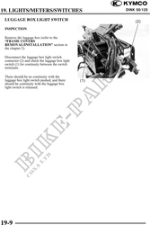
          19. LIGHTS/METERS/SWITCHES                                                       DINK 50/125
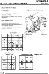


 HANDLEBAR SWITCH
                                                    Engine Stop Switch (DINK 125 only)
 INSPECTION

 Remove the front cover (refer to the
 "FRAME COVERS
 REMOVAL/INSTALLATION" section in
 the chapter 2).

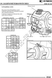
 Right handlebar switch

 Disconnect the right handlebar switch
 connector and check for continuity at switch
 side connector terminals.
 Continuity should exist between the color
 code wires as follows:


                                                Lighting Switch                  Starter Switch


                                                                  (DINK 125 only)


19-7