19. LIGHTS/METERS/SWITCHES DINK 50/125
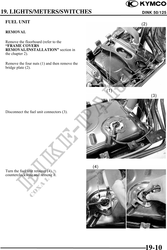
Remove the fuel unit (5).
Be careful not to bend or damage the
fuel unit float arm.
INSPECTION
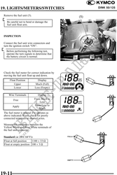
Connect the fuel unit wire connectors and
turn the ignition switch "ON".
Before performing the following test,
operate the turn signals to determine that
the battery circuit is normal.
Check the fuel meter for correct indication by
moving the fuel unit float up and down.
Float Position Display
Upper Much (Full)
Lower Less (Empty)
Wire Terminals Display
Free From Much to
Less
Apply From Less to
Much
The fuel meter is normal if it operates as
above indicated. If not, check for poorly
connected terminals or shorted wires.
Measure the resistance between the
Yellow/White and Blue/White terminals of
the fuel unit connector.
Standard (at 20°C/68°F):
Float at full position 1100 33
Float at empty position 100 3
19-11