dink 50 125 1 Werkplaats-Handboek : Bladzijde 56

Microfiches
Image preview

Bladzijde 54

Image preview

Bladzijde 55

Image preview

Bladzijde 57

Image preview

Bladzijde 58

1 5 10 15 20 25 30 35 40 45 50 55 60 65 70 75 80 85 90 95 100 105 110 115 120 125 130 135 140 145 150 155 160 165 170 175 180 185 190 195 200 205 210 215 220 225 230 235 240 245 250 255 260 265 270 275 280 285 290 295 300 305 310 315 320 325 330 335 340 345 350 355 360 365 370 375 380 385 390 395 400 405 410 415 420 424
          2. EXHAUST MUFFLER/FRAME COVERS                     DINK 50/125


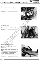
 Disconnect the headlight/position light
 connect and right/left turn signal light
 connectors.


 Installation is in the reverse order of removal.


 FRONT FENDER

 Remove the six screws and front fender.

 Installation is in the reverse order of removal.


 RIGHT/LEFT FOOT SKIRT

 Kick the button and make the passenger
 footpeg out.

 Remove the two screws and right or left foot
 skirt.
 During removal, do not pull the joint
   claws forcedly to avoid damage.


 Installation is in the reverse order of removal.


2-9