dink 50 125 1 Werkplaats-Handboek : Bladzijde 93

Microfiches
Image preview

Bladzijde 91

Image preview

Bladzijde 92

Image preview

Bladzijde 94

Image preview

Bladzijde 95

1 5 10 15 20 25 30 35 40 45 50 55 60 65 70 75 80 85 90 95 100 105 110 115 120 125 130 135 140 145 150 155 160 165 170 175 180 185 190 195 200 205 210 215 220 225 230 235 240 245 250 255 260 265 270 275 280 285 290 295 300 305 310 315 320 325 330 335 340 345 350 355 360 365 370 375 380 385 390 395 400 405 410 415 420 424
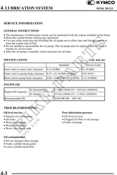
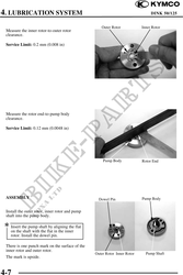
          4. LUBRICATION SYSTEM                                                            DINK 50/125
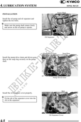

                                                                    Arrow Mark
 INSTALLATION

 Install the oil pump and oil separator and
 tighten the two bolts.
 Make sure the pump shaft rotates freely
   and arrow on the oil pump is upside.


                                                  Oil Separator               Bolts


                                                 Pump Drive Chain         Snap Ring

 Install the pump drive chain and driven gear,
 then set the snap ring securely on the pump
 shaft.


                                                             Pump Driven Gear


                                                                         Bolt
 Install the oil separator cover properly.

 Fit the tab of the separator cover into the
    slit in the separator.


                                                        Oil Separator Cover


4-5