5. ENGINE REMOVAL/INSTALLATION DINK 50/125
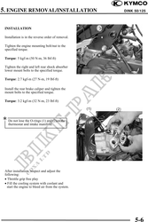
INSTALLATION
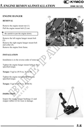
Installation is in the reverse order of removal.
Tighten the engine mounting bolt/nut to the
specified torque.
Torque: 5 kgf-m (50 N-m, 36 lbf-ft)
Tighten the right and left rear shock absorber
lower mount bolts to the specified torque.
Torque: 2.7 kgf-m (27 N-m, 19 lbf-ft)
Install the rear brake caliper and tighten the
mount bolts to the specified torque.
Torque: 3.2 kgf-m (32 N-m, 23 lbf-ft)
Do not lose the O-rings (1) and (2)on the
thermostat and intake manifold.
After installation, inspect and adjust the
following:
· Throttle grip free play
· Fill the cooling system with coolant and
start the engine to bleed air from the system.
5-6