5. ENGINE REMOVAL/INSTALLATION DINK 50/125
ENGINE HANGER
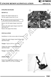
REMOVAL
Remove the engine mount nut (1).
Pull the engine mount bolt (2) out.
Be careful to put the engine down.
Remove the left engine hanger mount bolt
(3).
Remove the right engine hanger mount bolt
and collar (4).
Remove the engine from frame.
INSTALLATION
Installation is in the reverse order of removal.
Tighten the engine hanger mount bolts to the
specified torque.
Torque: 5 kgf-m (50 N-m, 36 lbf-ft)
Tighten the engine mount bolt/nut to the
specified torque.
Torque: 5 kgf-m (50 N-m, 36 lbf-ft)
INSPECTION
Inspect the engine hanger bushings (1) and
stopper rubber (2) for wear or damage.
5-8