dink 50 125 1 Werkplaats-Handboek : Bladzijde 121

Microfiches
Image preview

Bladzijde 119

Image preview

Bladzijde 120

Image preview

Bladzijde 122

Image preview

Bladzijde 123

1 5 10 15 20 25 30 35 40 45 50 55 60 65 70 75 80 85 90 95 100 105 110 115 120 125 130 135 140 145 150 155 160 165 170 175 180 185 190 195 200 205 210 215 220 225 230 235 240 245 250 255 260 265 270 275 280 285 290 295 300 305 310 315 320 325 330 335 340 345 350 355 360 365 370 375 380 385 390 395 400 405 410 415 420 424
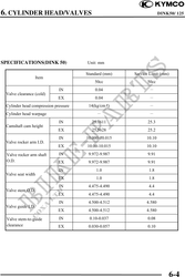
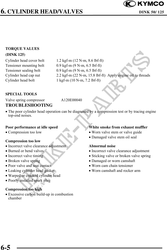
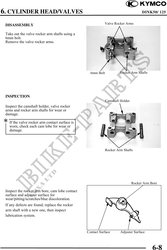
          6. CYLINDER HEAD/VALVES                                  DINK50/ 125
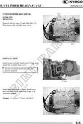


 CYLINDER HEAD COVER
 (DINK 125)
 REMOVAL

 Remove the two nuts (1) and four bolts (2),
 then remove the cylinder head cover.


 INSTALLATION

 Install a new cylinder head cover O-ring and
 install the cylinder head cover.
 Be sure to install the O-ring into the
    groove properly.


                                                O-ring


 Install and tighten the cylinder head cover
 bolts and nuts to the specified torque in a
 crisscross pattern.

 Torque: 1.2 kgf-m (12 N-m, 8.6 lbf-ft)


                                                             6-6