6. CYLINDER HEAD/VALVES DINK 50/ 125
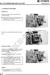
CAMSHAFT HOLDER
REMOVAL
Remove the four cap nuts/washers from
camshaft holder.
· Diagonally loosen the cylinder head
cap nuts in 2 or 3 times.
Camshaft Holder/Dowel Pins
Remove the camshaft holder and two dowel
pins.
INSTALLATION
Install the camshaft holder, washers and nuts.
Tighten the four cylinder head nuts to the
specified torque.
Torque: 2.2 kgf-m (22 N-m, 15.8 lbf-ft)
· Install the camshaft holder with the
"EX" mark face exhaust valve side.
· Apply engine oil to the threads of the
cylinder head cap nuts.
· Diagonally tighten the cylinder head
cap nuts in 23 times.
Adjust:
valve clearance (refer to the "VALVE
CLEARANCE" section in the chapter 3).
6-7