6. CYLINDER HEAD/VALVES DINK50/ 125
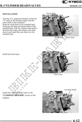
INSTALLATION Punch Marks
Turn the A.C. generator flywheel so that the
"T" mark on the flywheel aligns with the
index mark on the crankcase.
Keep the round hole on the camshaft gear
facing up and align the punch marks on the
camshaft gear with the cylinder head surface
(Position the intake and exhaust cam lobes
down.) and install the cam chain over the
camshaft gear.
Round Hole Cam Chain
Install the dowel pins.
Dowel Pins
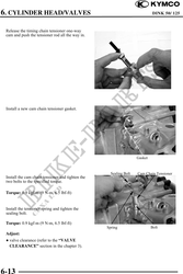
Camshaft Holder
Install the camshaft holder (refer to the
"CAMSHAFT HOLDER" section in this
chapter).
6-12