6. CYLINDER HEAD/VALVES DINK50/ 125
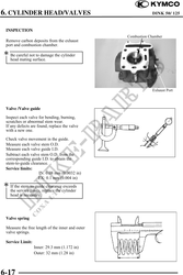
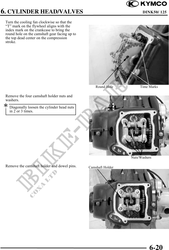
Cylinder head
Check the spark plug hole and valve areas for
cracks.
Check the cylinder head for warpage with a
straight edge and feeler gauge.
Service Limit: 0.05 mm (0.002 in)
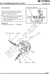
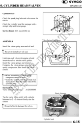
Valve Spring Compressor
ASSEMBLY
Install the valve spring seats and oil seal.
Be sure to install new oil seal.
Lubricate each valve with engine oil and
insert the valves into the valve guides.
Install the valve springs and retainers.
Compress the valve springs using the valve
spring compressor, then install the valve
cotters.
· When assembling, a valve spring
compressor must be used.
· Install the cotters with the pointed ends
facing down from the upper side of the
cylinder head.
Special tool:
Valve Spring Compressor A120E00040
Plastic Hammer
Tap the valve stems gently with a plastic
hammer for 23 times to firmly seat the
cotters.
Be careful not to damage the valves.
Cylinder head
6-18