6. CYLINDER HEAD/VALVES DINK 50/ 125
Cylinder Head Cover
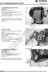
CYLINDER HEAD COVER
REMOVAL
Remove the rear body cover.
Disconnect the crankcase breather tube from
the cylinder head cover.
Disconnect the secondary air apply hose from
the cylinder head cover.
Remove the four bolts and two nuts from the
cylinder head cover, then remove the cylinder
head cover.
Nuts Bolts
INSTALLATION
Install a new cylinder head cover O-ring and
gasket.
Install the cylinder head cover.
Install and tighten the cylinder head cover
bolts and nuts.
Torque: 0.81.2kgf-m
Be sure to install the O-ring into the
groove properly.
O-ring Gasket
Tensioner Cap
CAMSHAFT/CAMSHAFT
HOLDER
REMOVAL
Remove the cylinder head cover. (Refer to
the "CYLINDER HEAD COVER
REMOVAL")
Remove the cam chain tensioner cap/spring.
Remove two bolts and cam chain tensioner.
Bolts
6-19