dink 50 125 1 Werkplaats-Handboek : Bladzijde 394

Microfiches
Image preview

Bladzijde 392

Image preview

Bladzijde 393

Image preview

Bladzijde 395

Image preview

Bladzijde 396

1 5 10 15 20 25 30 35 40 45 50 55 60 65 70 75 80 85 90 95 100 105 110 115 120 125 130 135 140 145 150 155 160 165 170 175 180 185 190 195 200 205 210 215 220 225 230 235 240 245 250 255 260 265 270 275 280 285 290 295 300 305 310 315 320 325 330 335 340 345 350 355 360 365 370 375 380 385 390 395 400 405 410 415 420 424
          17. IGNITION SYSTEM                                 DINK 50/125


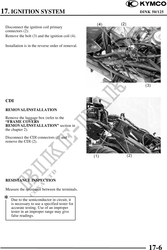
 Disconnect the ignition coil primary
 connectors (2).
 Remove the bolt (3) and the ignition coil (4).

 Installation is in the reverse order of removal.
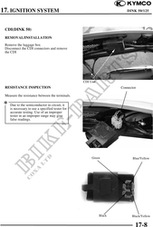


 CDI
 REMOVAL/INSTALLATION

 Remove the luggage box (refer to the
 "FRAME COVERS
 REMOVAL/INSTALLATION" section in
 the chapter 2).

 Disconnect the CDI connectors (1) and
 remove the CDI (2).


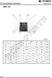
 RESISTANCE INSPECTION

 Measure the resistance between the terminals.

    Due to the semiconductor in circuit, it
    is necessary to use a specified tester for
    accurate testing. Use of an improper
    tester in an improper range may give
    false readings.


                                                        17-6