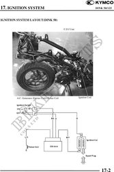
17. IGNITION SYSTEM DINK 50/125
IGNITION COIL INSPECTION
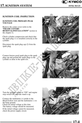
IGNITION COIL PRIMARY PEAK
VOLTAGE
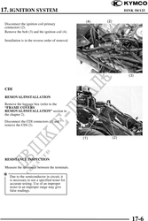
Remove the center cover (refer to the
"FRAME COVERS
REMOVAL/INSTALLATION" section in
the chapter 2).
Check cylinder compression and check that
the spark plug (1) is installed correctly in the
cylinder.
Disconnect the spark plug cap (2) from the
spark plug.
Connect known good spark plug to the spark
plug cap and ground the spark plugs to the
cylinder as done in the spark test.
Turn the ignition switch to "ON" and engine
stop switch ON and side stand is up.
Connect the multimeter (+) probe to the
Black/Yellow wire and the multimeter (-) to
the body ground.
Check for initial voltage at this time.
The battery voltage should be measured.
If the initial voltage cannot be measured,
check the power supply circuit.
17-4