16. BATTERY/CHARGING SYSTEM DINK 50/125
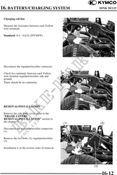
Charging coil line
Measure the resistance between each Yellow
wire terminals.
Standard: 0.40.6 (20C/68F)
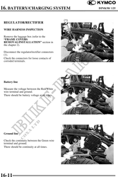
Disconnect the regulator/rectifier connector.
Check for continuity between each Yellow
wire terminal regulator/rectifier side and
ground.
There should be no continuity.
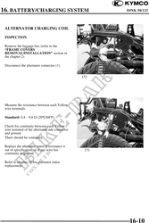
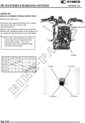
REMOVAL/INSTALLATION
Remove the side body cover (refer to the
"FRAME COVERS
REMOVAL/INSTALLATION" section in
the chapter 2).
Disconnect the regulator/rectifier connectors
(1).
Remove the two bolts (2), regulator/rectifier
(3).
Installation is in the reverse order of removal.
16-12